INSULATION CLASS OF ELECTRIC MOTORS DISCUSSION
How does electric motors being describe according to its insulation class?
NEMA
NEMA defines motor insulation classes to describe the ability of motor insulation to handle heat. The four insulation classes are A, B, F, and H. All four classes identify the allowable temperature rise from an ambient
temperature of 40° C (104° F). Classes B and F are the most commonly used. Ambient temperature is the temperature of the surrounding air. This is also the temperature of the motor windings before starting the motor, assuming the motor has been stopped long enough.
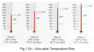
Fig.1.2A shows the allowable temperature rise for motors operated at a 1.0 service factor at altitudes no higher than 3300 ft. Each insulation class has a margin allowed to compensate for the motor’s hot spot, a point at the center of the motor’s windings where the temperature is higher. For motors with a service factor of 1.15, add 10° C to the allowed temperature rise for each motor insulation class.
How does electric motors being describe according to its insulation class?
NEMA
NEMA defines motor insulation classes to describe the ability of motor insulation to handle heat. The four insulation classes are A, B, F, and H. All four classes identify the allowable temperature rise from an ambient
temperature of 40° C (104° F). Classes B and F are the most commonly used. Ambient temperature is the temperature of the surrounding air. This is also the temperature of the motor windings before starting the motor, assuming the motor has been stopped long enough.
Temperature rises in the motor windings as soon as the motor is started. The combination of ambient temperature and allowed temperature rise equals the maximum rated winding temperature. If the motor is operated at a higher winding temperature, service life will be reduced. A 10° C increase in the operating temperature above the allowed maximum can cut the motor’s insulation life expectancy in half.
Fig.1.2A shows the allowable temperature rise for motors operated at a 1.0 service factor at altitudes no higher than 3300 ft. Each insulation class has a margin allowed to compensate for the motor’s hot spot, a point at the center of the motor’s windings where the temperature is higher. For motors with a service factor of 1.15, add 10° C to the allowed temperature rise for each motor insulation class.
Permitted output at high ambient temperature or high altitude above sea level. Motors in their standard versions are intended to operate in an ambient temperature of 40 °C maximum and at not more than 1000 meters above sea level. If the motors are to be used at higher ambient temperatures or higher altitudes the rated output must normally be reduced by the percentage shown in the Table 1.2A.
Insulation classes
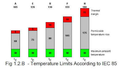
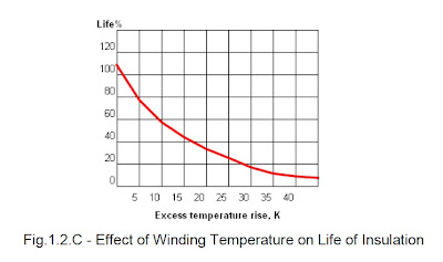
According to EC 85, insulation is divided into insulation classes. Each class has a designation corresponding to the temperature that is the upper limit of the range of application of the insulating material under normal operating conditions and with satisfactory life. If this upper limit exceeded by 8 to 10 K (see below), the Life of the Insulation will be approximately halved.
The correct insulation for the winding of a motor is therefore determined by both the temperature rise in the motor and the temperature of the ambient air. If a motor is subjected to an ambient temperature higher than 40 °C, it must normally be derated or an insulating material of a higher class must be used. According to international standards, temperature is measured in degrees Celsius (°C), whilst temperature difference is stated in the unit Kelvin (K). 1 Celsius degree is equivalent to 1 K.
For class F, for instance, the temperature rise must not exceed 105 K, provided that the ambient temperature does not exceed +40°C. This applies if the resistance measuring method is used. This involves first measuring the resistance of the winding at ambient temperature, then running a temperature-rise test of the motor to determine the temperature in the winding at rated power, then measuring the resistance of the winding at the end of the test.
What this method determines is the mean temperature rise. This is why an extra thermal margin of 10 K, for example, is reserved between the mean temperature of the winding and the temperature at its hottest point. The graph in Fig.1.2.C illustrates the effect of exceeding the highest permitted winding temperature on the winding life.
Source:IIEE Technical Manuals 2010 edition


They often work hand in hand in construction and plumber near me maintenance projects, each relying on the other's expertise to ensure that electrical and plumbing systems are installed and functioning properly.
ReplyDelete