
LINE LOSS CALCULATION: SAMPLE PROBLEM 2

PROBLEM: A 10-km, three phase transmission line delivers power to a load rated 2000kW, 6.9kV and at 80% lagging power factor. The resistance and reactance of each line are 0.2 and 1.2 ohms per kilometer, respectively. What percentage of the power generated is lost in the transmission line?

SOLUTION:

Similar to the previous problem, we should first draw the figure for us to understand clearly what is required for us to solve.

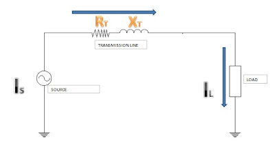
line loss

In this problem, we are asked to calculate the percentage of the power generated that was lost in the transmission line. Using the following given data below, we need to compute for the power that was lost in the line.
  • 10 km distance of the transmission line.
  • 2000kW load
  • 6.9kV voltage at 80% lagging power factor
  • line impedance of 0.2 +j1.2 ohms per km
Based upon the figure above, in order for us to compute for the line loss we should first solve for the line current.

LINE CURRENT = (kW) / (sqrt(3)*line voltage*power factor)

                             = (2,000,000) / (sqrt(3)*(6,900)*(0.8)

 LINE CURRENT = 209.185 A

After solving for the transmission line current, we now compute for the total line resistance for us to compute for the power loss in the line.

TOTAL IMPEDANCE = (0.2 + j1.2)ohms per km x 10km

                                     = 2 + j12 ohms

TOTAL RESISTANCE = 2 ohms

We then solve for the total lost power in the transmission line using the 3(IsquaredR) formula.

POWER LOSS = 3*I*I*R

                          =3(209.185)(209.185)(2)

POWER LOSS = 262.55 kW

Therefore,

POWER GENERATED = POWER LOAD + POWER LOSS

                                      = 2,000 +262.55

POWER GENERATED = 2262.55 kW

% Power Loss = Power Loss / Power Generated

                        = 262.55 / 2262.55

% Power Loss = 11.6%


Reference: 1001 Solved Problems in Electrical Engineering by Romeo Rojas Jr.

Comments

Popular posts from this blog

PARTS OF A POWER TRANSFORMER

What are the name of the basic parts of a Power Transformer? We can not deny the fact that only a handful of electrical engineering students are presently familiar with power transformers especially on what it looks like. Unlike a transformer we found in our homes, a power transformer’s appearance and construction is somewhat more complicated. It is not just a simple winding with a primary and secondary terminal although basically any transformer has one. The function that a power transformer plays in an electrical system is very important that an electric utility can not afford to loss it during its operation. Our discussion here will focus more on the basic parts and functions of a power transformer that are usually tangible whenever you go to a substation . Although not all power transformers are identical, nonetheless they all have the following listed parts in which the way of construction may differ.

ELECTRIC MOTOR FRAME SIZE STANDARD SPECIFICATIONS

ELECTRIC MOTOR FRAME SIZE STANDARD SPECIFICATIONS How is electric motor frame size being specified? Motor frame dimensions have been standardized with a uniform frame size numbering system. This system was developed by NEMA and specific frame sizes have been assigned to standard motor ratings based on enclosure, horsepower and speed. The current standardized frames for integral horsepower induction motors ranges from 143T to 445T. These standards cover most motors in the range of one through two hundred horsepower. Typical example of where you can locate the frame is shown in Fig 1.2.D – Frame No. The numbers used to designate frame sizes have specific meanings based on the physical size of the motor. Some digits are related to the motor shaft height and the remaining digit or digits relate to the length of the motor. The rerate, or frame size reduction programs were brought about by advancements in motor technology relating mainly to higher temperature ratings of insulating mate...

DISADVANTAGES OF Y-Y CONNECTION IN THREE PHASE SYSTEM

What are the disadvantages in using y-y connection? The Y-Y transformer connection was poorly understood in the early days of power engineering and it received a very bad reputation when it was first used; in fact, this connection was avoided for a long time until its limitations were overcome by good engineering practice. Some of the inherent disadvantages of the Y-Y connection are discussed below: