TRANSFORMER LOSSES AND THE EFFECT OF HARMONIC CURRENTS ON THESE LOSSES TUTORIAL DISCUSSION (From ANNEX D of IEEE STD C57.110-1998)
TRANSFORMER LOSSES AND THE EFFECT OF HARMONIC CURRENTS ON THESE LOSSES TUTORIAL DISCUSSION (From ANNEX D of IEEE STD C57.110-1998)
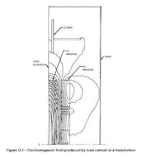
The inner winding of a core form transformer typically has higher eddy-current loss than the outer winding, because the electromagnetic flux has a greater tendency to fringe inwardly toward the low reluctance path of the core leg. Furthermore, the highest local eddy-current loss usually occurs in the end conductors of the inside winding. This is a result of the fact that this is the region of highest radial electromagnetic flux density (closest spacing of the radially directed flux lines in Figure D.1) and the radial flux passes through the width dimension of the rectangular winding conductor. Since the width dimension of a conductor is typically 3-5 times the thickness dimension and eddy-current loss is proportional to the square of the dimension, high loss is produced in the end conductors.
Certain simplifying assumptions have been made in this recommended practice about the relative proportions of the eddy-current losses in the inner and outer windings and the relation between average eddy-current losses and maximum local eddy-current losses. These assumptions, which are conservative, may be used when specific knowledge of the eddy-current loss magnitude is not available. However, more accurate calculations can be made if design values of eddy-current losses are available from the transformer manufacturer.
The recommendations for determination of acceptable operating conditions contained in this recommended practice are based on the calculation of a “transformer capability equivalent,” which establishes a current derating factor for load currents having a given harmonic composition. Equation (17) provides a calculation of the maximum rms value of a non-sinusoidal load current (in per unit of rated load current) that will ensure that the losses in the highest loss density region of the windings do not exceed the design value of losses under rated frequency operating conditions.
Example cases are presented for the situations where design eddy-current loss data are available from the manufacturer or where they are not. Harmonic currents flowing through transformer leakage impedance and through system impedance may also produce some small harmonic distortion in the voltage waveform at the transformer terminals. Such voltage harmonics also cause extra harmonic losses in the transformer core. However, operating experience has not indicated that core temperature rise will ever be the limiting parameter for determination of safe magnitudes of non-sinusoidal load currents.
Power transformers with ratings up to 50 MVA are almost always of core form construction. High-voltage and low-voltage windings are concentric cylinders surrounding a vertical core leg of rectangular or circular cross section. The vertical core legs and the horizontal core yoke members that constitute the magnetic circuit are made up of thin steel laminations. In the top and bottom yoke regions there are usually external clamping structures (clamps) that may be made of either metallic or insulating materials. Oil-immersed transformers are contained within a steel tank, while dry-type transformers may be either freestanding or surrounded by a metal enclosure. If direct current is passed through the transformer winding conductors, a simple I 2R loss will be produced, where R is the dc resistance of the winding.
However, if an alternating current (ac) of the same magnitude is passed through the winding conductors, an additional loss is produced. This can be explained as follows. When the transformer windings carry the ac current, each conductor is surrounded by an alternating electromagnetic field whose strength is directly proportional to the magnitude of the current.
A picture of the composite field produced by rated load current flowing through all the winding conductors is shown in Figure D.1, which is a cross-sectional view through the core, windings, clamps, and tank. Each metallic conductor linked by the electromagnetic flux experiences an internal induced voltage that causes eddy currents to flow in that conductor. The eddy currents produce losses that are dissipated in the form of heat, producing an additional temperature rise in the conductor over its surroundings. This type of extra loss beyond the I2R loss is frequently referred to as “stray loss.” Although all of the extra loss is an eddy-current loss, the portion in the windings is usually called “eddy-current loss” (PEC), and the portion outside the windings is called “other stray loss” (POSL).

Eddy-current loss in winding conductors is proportional to the square of the electromagnetic field strength (or the square of the load current that produces the field) and to the square of the ac frequency. Other stray losses are generally proportional to current raised to a power slightly less than 1, because the depth of penetration of the electromagnetic flux into the other metallic parts (usually steel) varies with the field strength. (For very high-frequency harmonic currents the electromagnetic flux may not totally penetrate the winding conductors either, but it is conservative to assume that the eddy-current loss, PEC, is proportional to the square of the harmonic current frequency.)
When a transformer is subjected to a load current having significant harmonic content, the extra eddy-current loss in winding conductors and in other metallic parts will elevate the temperature of those parts above their normal operating temperature under rated conditions. Experience has shown that the winding conductors are the more critical parts for determination of acceptable operating temperature, so the objective should be to prevent the losses in winding conductors under harmonic load conditions from exceeding the losses under rated frequency operating conditions.
The inner winding of a core form transformer typically has higher eddy-current loss than the outer winding, because the electromagnetic flux has a greater tendency to fringe inwardly toward the low reluctance path of the core leg. Furthermore, the highest local eddy-current loss usually occurs in the end conductors of the inside winding. This is a result of the fact that this is the region of highest radial electromagnetic flux density (closest spacing of the radially directed flux lines in Figure D.1) and the radial flux passes through the width dimension of the rectangular winding conductor. Since the width dimension of a conductor is typically 3-5 times the thickness dimension and eddy-current loss is proportional to the square of the dimension, high loss is produced in the end conductors.
Certain simplifying assumptions have been made in this recommended practice about the relative proportions of the eddy-current losses in the inner and outer windings and the relation between average eddy-current losses and maximum local eddy-current losses. These assumptions, which are conservative, may be used when specific knowledge of the eddy-current loss magnitude is not available. However, more accurate calculations can be made if design values of eddy-current losses are available from the transformer manufacturer.
The recommendations for determination of acceptable operating conditions contained in this recommended practice are based on the calculation of a “transformer capability equivalent,” which establishes a current derating factor for load currents having a given harmonic composition. Equation (17) provides a calculation of the maximum rms value of a non-sinusoidal load current (in per unit of rated load current) that will ensure that the losses in the highest loss density region of the windings do not exceed the design value of losses under rated frequency operating conditions.
Example cases are presented for the situations where design eddy-current loss data are available from the manufacturer or where they are not. Harmonic currents flowing through transformer leakage impedance and through system impedance may also produce some small harmonic distortion in the voltage waveform at the transformer terminals. Such voltage harmonics also cause extra harmonic losses in the transformer core. However, operating experience has not indicated that core temperature rise will ever be the limiting parameter for determination of safe magnitudes of non-sinusoidal load currents.
Comments
Post a Comment