TRANSFORMER PARALLELING TUTORIAL & DOWNLOAD
 However, there are times when all of these factors are quite insignificant compared to an underlying consideration. Paralleling of transformers are usually practiced whenever, in any service, there should be continuity of supply of power or at least a partial service in times of transformer failure of one unit is of tremendous importance like in hospital operation, production, etc. According to IEEE, among the major reasons why transformer paralleing is exercised is to have an additional capacity, standardize transformer rating, security/contingencies, and maintenace purposes.
In actual electrical engineering application, sometimes an engineer would sacrifice logic in order for him to achieve a greater purpose. Unlike in theory, actual engineering practice requires decision making situations where we base our decisions on more than just what we compute and what we think as the most correct action. Say for instance in paralleling tansformers, generally, it is not recommended to use two smaller size transformers, to be used in one circuit by paralleling in replacement for using a single full-size transformer with the same capacity with latter set-up. Logically speaking, utilizing two transformers will be more expensive compared to using a single unit transformer both with the same transformation capacity. Not to mention the fact that the combined losses of two transformer will be higher to that of a single transformer especially when it comes to its no-load loss considerations. Also, a two-unit transformer will need a larger substation space and structures to accomodate them.
 However, there are times when all of these factors are quite insignificant compared to an underlying consideration. Paralleling of transformers are usually practiced whenever, in any service, there should be continuity of supply of power or at least a partial service in times of transformer failure of one unit is of tremendous importance like in hospital operation, production, etc. According to IEEE, among the major reasons why transformer paralleing is exercised is to have an additional capacity, standardize transformer rating, security/contingencies, and maintenace purposes.
In transformer parallel operation, several factors are strictly followed in paralleling transformers, both units should have in the same or similar magnitude of the following;
- Voltage Ratio
- Impedance
- Voltage Taps
- Polarity and Phase Voltage Displacement
To explain things up, having the same impedance is necessary since equal transformer impedance will yield proportionate loading to each of the transformer used. Since if their impedances are not the same, the loading will be divided inversely proportional to the impedance of the transformer. This issue is very significant when using transformer of different kVA rating. When a smaller kVA tranformer possesses an impedance lower to the other, there wll be a huge possiblity of overloading the said transformer while the larger transformer with higher impedance on the other hand will still have more capacity.
Furthermore, in paralleling transformer proper transformer protection should also be observed. It is not recommend to treat a transformer in parallel as a single unit since usually incorrect differential relay are neglected.
Voltages of the two transformer should also be carefully look into since when paralleling two tranformers with different voltage level will result to circulting current. Excessive circlating currents in the transformers will result to transformer overloading and transformer loss of life due to overheating. Likewise, the same phase rotation and polarity should also be observed in paralleling. An error in phase polarity during paralleling could result to a line-line fault that could be not only damaging to the transformer but could also be extremely dangerous to the personnel nearby.
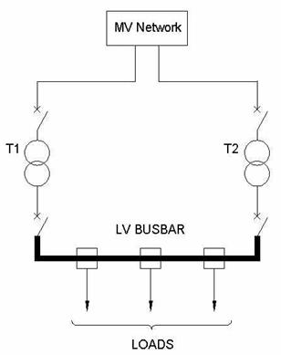
WHAT IS TRANSFORMER PARALLELING?
WHAT IS TRANSFORMER PARALLELING?
"Two or more transformers connected in such a
manner that they share in the supply to a
common load bus."
manner that they share in the supply to a
common load bus."
-IEEE/PES Transformer Committee
or you could also refer to the RUS Bulletin 1724E-300 Chapter 5.2.7 Parallel Operation ofTransformers Page 202.
Good information Transformers tutorials. Thanks!
ReplyDeletePower transformers in India | Transformer manufacturer in India