TYPES OF CAPACITOR INSTALLATIONS
What are the types of Capacitor Installation known?
What are the types of Capacitor Installation known?
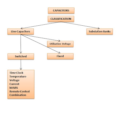
Capacitors are relatively easy to install and are among the most trouble-free electrical devices. Line capacitor installations are protected with conventional cut-out fused switches, and capacitor failure is rare if the appropriate fuse element is used. (Fuse rating should be closely coordinated with capacitor size.) There are several types of capacitors (see figure below).
Following Load Reactive Power
The most difficult aspect of capacitor application is the maintenance of proper balance between total kVAR of capacitors connected at any particular time and load kVAR present at that time. Like load kW, load kVAR changes over time, so some provision must be made to vary the total connected capacitive kVAR to roughly follow the load kVAR. Installing capacitors based on the peak load kVAR and leaving all these capacitors connected at off-peak times is strictly inadvisable, since excessive capacitive kVAR would exist on the system during light load periods. This would result in an overall leading power factor for the feeder involved, and a leading power factor increases line amperes in the same manner that a lagging power factor does. A leading power factor can cause other problems also, such as excessive line voltage and harmonics.
An example of the consequences of failing to remove capacitors that are too large for the load kVAR occurred on part of the system of an actual rural electric cooperative. A 600-kVAR capacitor was installed near the location of an industrial consumer, and the capacitor was not removed after the consumer went out of business. The losses on the small whole sale metering point increased from 3.5% to 23%. The cause was not immediately identified because power-factor metering at the supply point indicated that the power factor was 85%, but it did not identify whether the power factor was leading or lagging. In this case, the power factor was leading because of the excessive capacitive kVAR on the feeder. In addition to the above reasons, distributors should avoid leading kVAR because the Reactive Demand Charges clause of the TVA WS rate schedule contains charge for leading power factor at delivery points. The charge is 33 cents per leading kVAR at the time of minimum load for each month. This seemingly modest charge can accumulate into a significant amount in dollars if hundreds of leading kVAR are present month after month.
Switched and Fixed Capacitors
The total kVAR of connected capacitors is controlled by installing automatic switching on some of the capacitors. The units equipped with switches, called switched capacitors are removed from the line during light load periods so the remaining connected capacitive kVAR will closely agree with the load kVAR. Since a base amount of load kVAR remains even during minimum load, some capacitors can be connected permanently to the line. Capacitors that remain connected to the line at all times are called fixed capacitors.
Comments
Post a Comment