What are the basic parts of an electro-mechanical meter?
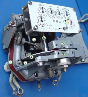
4. Aluminium rotor disc.
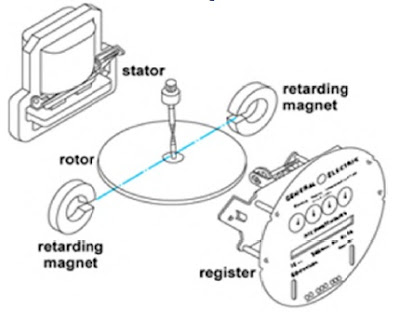
Construction
A typical electro-mechanical/ induction type wattmeter is made up of the following; an aluminium disc mounted on a spindle, a current coil and a voltage coil, a permanent magnet and a counter. The current coil is connected in series with the load and the voltage coil connected across the supply.
A typical electro-mechanical/ induction type wattmeter is made up of the following; an aluminium disc mounted on a spindle, a current coil and a voltage coil, a permanent magnet and a counter. The current coil is connected in series with the load and the voltage coil connected across the supply.
These two coils generate magnetic fields, and are arranged in such a manner that, the eddy currents developed in the disk forces the aluminium disc to rotate and the permanent magnet acts as a brake on the disc. The disc rotates at a speed N which is proportional to power. The worm and the worm wheel provided with the spindle moves the counter.

1. Potential coil
A Voltage Coil Assembly consists of a coil with many turns of fine wire and laminated core. The voltage coil is designed to produce air gap magnetic flux, which is proportional to the applied voltage.
A Voltage Coil Assembly consists of a coil with many turns of fine wire and laminated core. The voltage coil is designed to produce air gap magnetic flux, which is proportional to the applied voltage.
2. Current coil
A Current Coil Assembly consists of a relatively few turns of large cross-section conductor and a laminated core assembly. The current coil assembly must produce air gap magnetic flux, which is proportional to the current drawn by the load.
A Current Coil Assembly consists of a relatively few turns of large cross-section conductor and a laminated core assembly. The current coil assembly must produce air gap magnetic flux, which is proportional to the current drawn by the load.
3. Meter stator
The stator of a Kilowatt-hour meter consists of two sub-assemblies: a voltage coil and core assembly, and a current coil and core assembly. These two assemblies are precisely located on the frame to establish an air gap through which the meter disk rotates.
The stator of a Kilowatt-hour meter consists of two sub-assemblies: a voltage coil and core assembly, and a current coil and core assembly. These two assemblies are precisely located on the frame to establish an air gap through which the meter disk rotates.

5. Rotor brake magnets.
6. Spindle with worm gear.
7. Display dials
Note that the 1/10, 10 and 1000 dials rotate clockwise while the 1, 100 and 10000 dials rotate counter-clockwise.
Fantastic material - Many thanks for putting up that advice, I believe that it mostly answers my question.
ReplyDeleteb2b businesses
Great breakdown of electric meter parts and their working principles!
ReplyDeleteUnderstanding how the voltage and current coils interact to drive the aluminium disc really clarifies the role of electromagnetic forces in power measurement. The counter-rotating dials and braking system also highlight the precision engineering behind these devices. A helpful read for anyone exploring traditional energy metering!
This blog gives a clear understanding of how electromechanical assemblies contribute to product performance and reliability.
ReplyDeleteBest Electromechanical assembly manufacturers in USA.