STANDARD REQUIREMENTS IN DEALING WITH CURRENT TRANSFORMERS
What is a Current Transformer with respect to C57.13?
Terms in which ratings shall be expressed
The ratings of a current transformer shall include:
a) Basic impulse insulation level in terms of full-wave test voltage.
b) Nominal system voltage, or maximum system voltage.
c) Frequency (in Hertz)
d) Rated primary and secondary currents.
e) Accuracy classes at standard burdens.
f) Continuous thermal current rating factor based on 30 °C average ambient air temperature.
g) Short-time mechanical current rating and short-time thermal current rating.
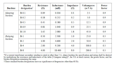
Standard burdens
Standard burdens for current transformers with 5 A rated secondary current shall have resistance and inductance according to table below.
Standard burdens for current transformers with 5 A rated secondary current shall have resistance and inductance according to table below.

Accuracy ratings for metering
A current transformer for metering shall be given an accuracy rating for each standard burden for which it is rated. For example, the accuracy ratings assigned to a current transformer might be 0.3 B-0.1 and B-0.2, 0.6 B-0.5.
Tapped-secondary or multiple-ratio current transformer accuracy rating - The metering accuracy rating applies to the full secondary winding, unless otherwise specified.
Accuracy ratings for relaying
A current transformer for relaying shall be given an accuracy rating according to the statement above.
>>Basis for relaying accuracy ratings
For relaying accuracy ratings, the ratio correction shall not exceed 10%. Relaying accuracy ratings shall be designated by a classification and a secondary terminal voltage rating as follows:
a) C, K, or T, classification. C or K classification covers current transformers in which the leakage flux in the core of the transformer does not have an appreciable effect on the ratio or ratios within the limits of current and burden outlined in this subclause, so that the ratio can be calculated in accordance with 8.1.10. Current transformers with K classification shall have a knee-point voltage (see 6.10.2) at least 70% of the secondary terminal voltage rating.
T classification covers current transformers in which the leakage flux in the core of the transformer has an
appreciable effect on the ratio within the limits specified in item b.
An appreciable effect is defined as a 1% difference between the values of actual ratio correction and the ratio
correction calculated in accordance with 8.1.10.
b) Secondary terminal voltage rating. This is the voltage the transformer will deliver to a standard burden at 20 times rated secondary current without exceeding 10% ratio correction. Furthermore, the ratio correction shall be limited to 10% at any current from 1 to 20 times rated secondary current at the standard burden or any lower standard burden used for secondary terminal voltage ratings. For example, on a current transformer with 5 A rated secondary current, relay accuracy rating C100 means that the ratio can be calculated and that the ratio correction will not exceed 10% at any current from 1 to 20 times rated secondary current with a standard 1.0 ohm burden (1.0 W ´ 5 A ´ 20 ´ rated secondary current = 100 V). Secondary terminal voltage ratings are based on a rated secondary current of 5 A (100 A at 20 times rated) and standard burdens. The voltage ratings and their associated burdens are as follows:

If a current transformer secondary winding is rated at other than 5 A, appropriate voltage rating values shall be derived by multiplying the standard voltage rating values by 5/(amperes rating). For such transformers, the burden will be derived as in table 11 and the secondary terminal voltage rating will be the resulting value at 20 times rated secondary current. For example, if the rated secondary current is 1 A, the burden corresponding to B-2.0 will be 2.0 ´ 25, or 50 W (at 0.5 power factor); and the corresponding secondary terminal voltage rating will be 50 ´ 20 ´ 1 = 1000 V. In this example, the relay accuracy rating would be C1000, K1000, or T1000 as applicable.
Short-time current ratings
The short-time thermal current and short-time mechanical capabilities are not independent.
- Short-time mechanical current rating
- Short-time thermal current rating
- Short-time and continuous current ratings of window-type or bushing-type current transformers
Nameplates
Nameplates shall include, as a minimum, the following:
a) Manufacturer's name or trademark
b) Manufacturer's type
c) Manufacturer's serial number (SER)
d) Rated primary and secondary current
e) Nominal system voltage (NSV) or maximum system voltage (MSV) (None for bushing CTs)
f) Basic impulse insulation level (BIL kV) (None for bushing CTs)
g) Rated frequency (Hz)
h) Continuous thermal current rating factor (RF)
i) Accuracy rating
1) Metering accuracy class at a specified standard burdens: as a minimum, the burdens at which the
transformer is rated 0.3 accuracy class
2) Relaying accuracy rating on transformers intended primarily for relaying applications
NOTE — See IEEE Std C37.04-1979 and NEMA SG 4.1975 for nameplate requirements in high-voltage circuit breakers.
Terminals
Primary terminals of wound-type and bar-type current transformers shall be suitable for use with either aluminum or copper conductors. Secondary terminals and voltage terminals, where provided, shall be suitable for use with copper conductors.
Primary terminals of wound-type and bar-type current transformers shall be suitable for use with either aluminum or copper conductors. Secondary terminals and voltage terminals, where provided, shall be suitable for use with copper conductors.
Comments
Post a Comment