ELECTRIC INDUCTION MOTOR DESIGN: NEMA MOTOR DESIGN LETTER GUIDE
What are the motor design types that are provided by NEMA?
The four NEMA (National Electrical Manufacturers Association) designs have unique speed-torque-slip relationships making them suitable to different type of applications:
NEMA design A
Has maximum 5% slip, high to medium starting current, normal locked rotor torque, normal breakdown torque, and suited for a broad variety of applications - as fans and pumps.
NEMA design C
Has maximum 5% slip, low starting current, high locked rotor torque, normal breakdown torque, and suited for equipment with high inertia starts - as positive displacement pumps.
NEMA design D
Has maximum 5% slip, low starting current, very high locked rotor torque, and suited for equipment with very high inertia starts - as cranes, hoists etc.
What are the motor design types that are provided by NEMA?
NEMA Design Letter
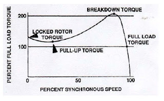
Changes in motor windings and rotor design will alter the performance characteristics of induction motors. Motors are designed with certain speed torque characteristics to match the speed torque requirements of the various loads. To obtain some uniformity in application, NEMA has designated specific designs of general purpose motors having specified locked rotor torque, breakdown torque, slip, starting current, or other values. The following graph shows the relationship between speed and torque that the motor produces from the moment of start until the motor reaches full load torque at rated speed.

NEMA has established four different designs - A, B, C and D - for electrical induction motors. Different motors of the same nominal horsepower can have varying starting current, torque curves, speeds, and other variables. Selection of a particular motor for an intended task must take all engineering parameters into account.
The four NEMA (National Electrical Manufacturers Association) designs have unique speed-torque-slip relationships making them suitable to different type of applications:
NEMA design A
Has maximum 5% slip, high to medium starting current, normal locked rotor torque, normal breakdown torque, and suited for a broad variety of applications - as fans and pumps.
NEMA design B
Has maximum 5% slip, low starting current, high locked rotor torque, normal breakdown torque, suited for a broad variety of applications, normal starting torque - common in HVAC application with fans, blowers and pumps.
Has maximum 5% slip, low starting current, high locked rotor torque, normal breakdown torque, suited for a broad variety of applications, normal starting torque - common in HVAC application with fans, blowers and pumps.
NEMA design C
Has maximum 5% slip, low starting current, high locked rotor torque, normal breakdown torque, and suited for equipment with high inertia starts - as positive displacement pumps.
NEMA design D
Has maximum 5% slip, low starting current, very high locked rotor torque, and suited for equipment with very high inertia starts - as cranes, hoists etc.
source: 2010 IIEE Technical Manuals for Electric Motors
Comments
Post a Comment