ELECTRIC MOTOR MOUNTING USING NEMA DIMENSIONS TUTORIAL GUIDE
What are the guidelines in mounting electric motors using NEMA?
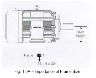
Motors that have a U in their motor frame size designation are built to NEMA standards that were in place between 1952 and 1964. The frame size designation is a code to help identify key frame dimensions. The first two digits are used to determine the shaft height. The shaft height is the distance from the center of the shaft to the mounting surface. To calculate the shaft height, divide the first two digits of the frame size by 4. For example, In Fig. 1.5A - a 143T frame size motor has a shaft height of 3½ inches (14 ÷ 4).
What are the guidelines in mounting electric motors using NEMA?
NEMA has standardized motor dimensions for a range of frame sizes. Standardized dimensions include bolt-hole size, mounting base dimensions, shaft height, shaft diameter, and shaft length. Use of standardized dimensions allows existing motors to be replaced without reworking the mounting arrangement. In addition, new installations are easier to design because the dimensions are known.
NEMA divides standard frame sizes into two categories, fractional horsepower and integral horsepower. The most common frame sizes for fractional horsepower motors are 42, 48, and 56. Integral horsepower motors are designated by frame sizes 143 and above. A T in the motor frame size designation for an integral horsepower motor indicates that the motor is built to current NEMA frame standards.
Motors that have a U in their motor frame size designation are built to NEMA standards that were in place between 1952 and 1964. The frame size designation is a code to help identify key frame dimensions. The first two digits are used to determine the shaft height. The shaft height is the distance from the center of the shaft to the mounting surface. To calculate the shaft height, divide the first two digits of the frame size by 4. For example, In Fig. 1.5A - a 143T frame size motor has a shaft height of 3½ inches (14 ÷ 4).

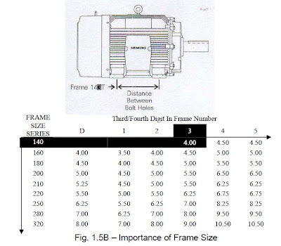
The third digit in the integral T frame size number is the NEMA code for the distance between the center lines of the motor feet mounting bolt holes. The distance is determined by matching this digit with a table in NEMA publication MG-1. For example in Fig. 1.5B, the distance between the center lines of the mounting bolt holes in the feet of a 143T frame is 4.00 inches.

source: 2010 IIEE Technical Manuals for Motors
Comments
Post a Comment