TYPES OF FUSES FOR ELECTRIC MOTORS PROTECTION

TYPES OF FUSES FOR ELECTRIC MOTORS PROTECTION
Different types of fuses for electric motor protection
Fuses are over-current protective devices that are placed in an electrical circuit to protect the control components, wiring, insulation, and motor from damage caused by excessive current and associated heat. Overcurrents are considered any increase in continuous current above the normal operating current level. In motor circuits, overcurrents are classified in two different categories. Motor overloads are any overcurrents up to or slightly above locked rotor current (6-8 times FLA).

This range of overcurrent is protected by overload relay protection devices which will be discussed in more detail later. Short-circuit overcurrents are those produced by short-circuit or ground fault conditions with fault current levels in excess of 8 times FLA.

In today’s industrial facilities, short-circuit overcurrents can easily reach 50,000A. If the short-circuit overcurrents are not interrupted within fractions of a second, severe damage to the electrical installation can occur including motor damage, conductor and controller damage or even fires.

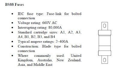
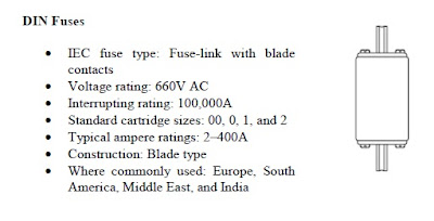
In motor circuits, fuses best provide protection from damage caused by short–circuit currents. Throughout the world, many different types of fuses are used for shortcircuit protection in motor circuits. In North America, UL and CSA fuses are most commonly used. In other parts of the world, DIN (German) and BS88 (British) fuses are dominant. Even though the construction and fastening means are quite different (See different types of fuses below), all these fuses still perform the same essential function of short-circuit protection.

Different Types of Fuses
bs88 fuse
din fuses


ul/csa fuses


current limiting fuse

Comments

Post a Comment

Popular posts from this blog

PARTS OF A POWER TRANSFORMER

What are the name of the basic parts of a Power Transformer? We can not deny the fact that only a handful of electrical engineering students are presently familiar with power transformers especially on what it looks like. Unlike a transformer we found in our homes, a power transformer’s appearance and construction is somewhat more complicated. It is not just a simple winding with a primary and secondary terminal although basically any transformer has one. The function that a power transformer plays in an electrical system is very important that an electric utility can not afford to loss it during its operation. Our discussion here will focus more on the basic parts and functions of a power transformer that are usually tangible whenever you go to a substation . Although not all power transformers are identical, nonetheless they all have the following listed parts in which the way of construction may differ.

ELECTRIC MOTOR NAMEPLATE SPECIFICATIONS

How do we interpret an electric motor nameplate? Motor standards are established on a country by country basis.Fortunately though, the standards can be grouped into two major categories: NEMA and IEC (and its derivatives). In North America, the National Electric Manufacturers Association (NEMA) sets motor standards, including what should go on the nameplate (NEMA Standard MG 1-10.40 "Nameplate Marking for Medium Single-Phase and Polyphase Induction Motors").

DISADVANTAGES OF Y-Y CONNECTION IN THREE PHASE SYSTEM

What are the disadvantages in using y-y connection? The Y-Y transformer connection was poorly understood in the early days of power engineering and it received a very bad reputation when it was first used; in fact, this connection was avoided for a long time until its limitations were overcome by good engineering practice. Some of the inherent disadvantages of the Y-Y connection are discussed below: