TYPES OF IMPEDANCE FAULT IN DISTRIBUTION SYSTEM
Low Impedance and High Impedance fault in the distribution system
High Impedance Faults
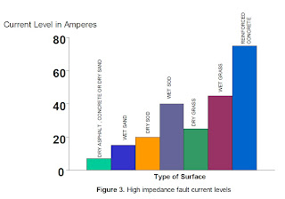
High impedance faults are faults that are low in value, i.e., generally less than 100 amperes due to the impedance between the phase conductor and the surface on which the conductor falls. Figure 3, shown below, illustrates that most surface areas whether wet or dry do not conduct well. If one considers the fact that an 8 foot ground rod sunk into the earth more often than not results in an impedance of 100 ohms or greater, then it is not hard to visualize the fact that a conductor simply lying on a surface cannot be expected to have a low impedance. These faults, called high impedance faults, do not contact the neutral and do not arc to the neutral. They are not detectable by any conventional means and are not to be considered at all in the evaluation of FCIs and most other protective devices.
Low Impedance and High Impedance fault in the distribution system
Low Impedance Faults
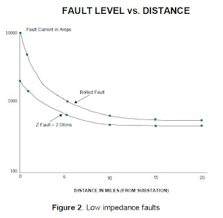
Low impedance faults or bolted faults can be either very high in current magnitude (10,000 amperes or above) or fairly low, e.g., 300 amperes at the end of a long feeder. Faults able to be detected by normal protective devices are all low impedance faults. These faults are such that the calculated value of fault current assuming a "bolted fault” and the actual are very similar. Most detectable faults, per study data, do indeed show that fault impedance is close to 0 ohms. This implies that the phase conductor either contacts the neutral wire or that the arc to the neutral conductor has a very low impedance. An EPRI study performed by the author over 10 years ago indicated that the maximum fault impedance for a detectable fault was 2 ohms or less. Figure 2, shown below, indicates that 2 ohms of fault impedance influences the level of fault current depending on location of the fault. As can be seen, 2 ohms of fault impedance considerably decreases the level of fault current for close in faults but has little effect for faults some distance away. What can be concluded is that fault impedance does not significantly affect faulted circuit indicator performance since low level faults are not greatly altered.
Low impedance faults or bolted faults can be either very high in current magnitude (10,000 amperes or above) or fairly low, e.g., 300 amperes at the end of a long feeder. Faults able to be detected by normal protective devices are all low impedance faults. These faults are such that the calculated value of fault current assuming a "bolted fault” and the actual are very similar. Most detectable faults, per study data, do indeed show that fault impedance is close to 0 ohms. This implies that the phase conductor either contacts the neutral wire or that the arc to the neutral conductor has a very low impedance. An EPRI study performed by the author over 10 years ago indicated that the maximum fault impedance for a detectable fault was 2 ohms or less. Figure 2, shown below, indicates that 2 ohms of fault impedance influences the level of fault current depending on location of the fault. As can be seen, 2 ohms of fault impedance considerably decreases the level of fault current for close in faults but has little effect for faults some distance away. What can be concluded is that fault impedance does not significantly affect faulted circuit indicator performance since low level faults are not greatly altered.

High Impedance Faults
High impedance faults are faults that are low in value, i.e., generally less than 100 amperes due to the impedance between the phase conductor and the surface on which the conductor falls. Figure 3, shown below, illustrates that most surface areas whether wet or dry do not conduct well. If one considers the fact that an 8 foot ground rod sunk into the earth more often than not results in an impedance of 100 ohms or greater, then it is not hard to visualize the fact that a conductor simply lying on a surface cannot be expected to have a low impedance. These faults, called high impedance faults, do not contact the neutral and do not arc to the neutral. They are not detectable by any conventional means and are not to be considered at all in the evaluation of FCIs and most other protective devices.

source: ABB Inc.HARD TO FIND INFORMATIONABOUT DISTRIBUTION SYSTEMS
Great Blog,Thanks for sharing such beautiful information with us. I hope to will share some more information about Arc flash protection levels. Please visit our website Arc flash protection levels
ReplyDeleteSources?
ReplyDelete